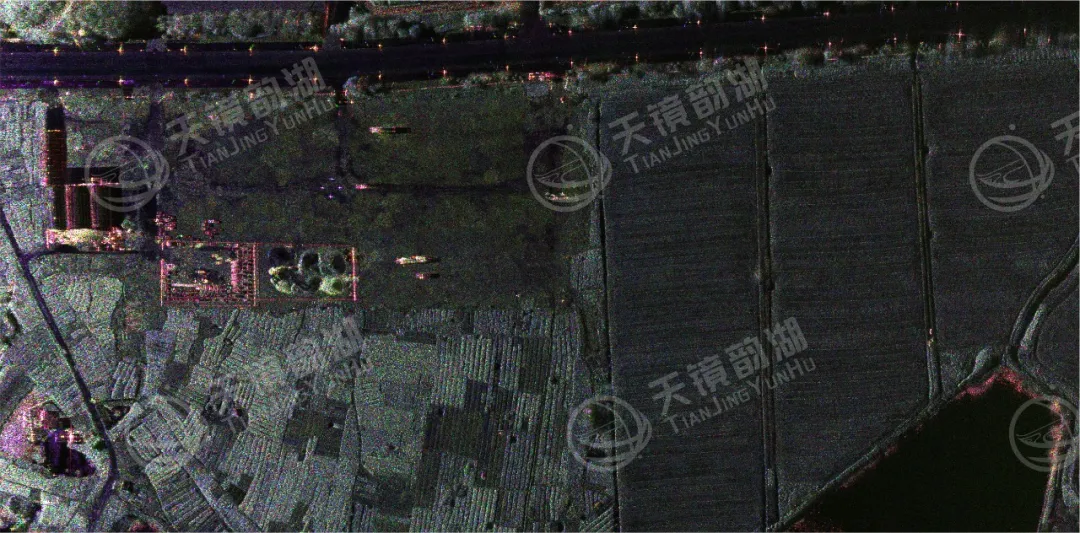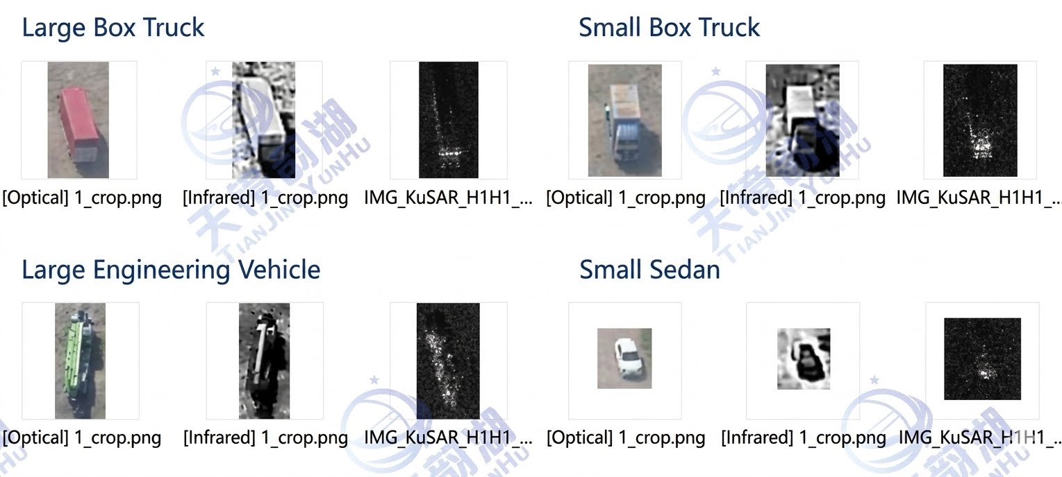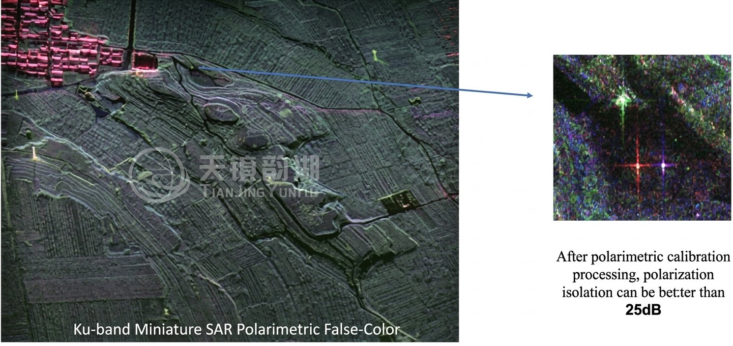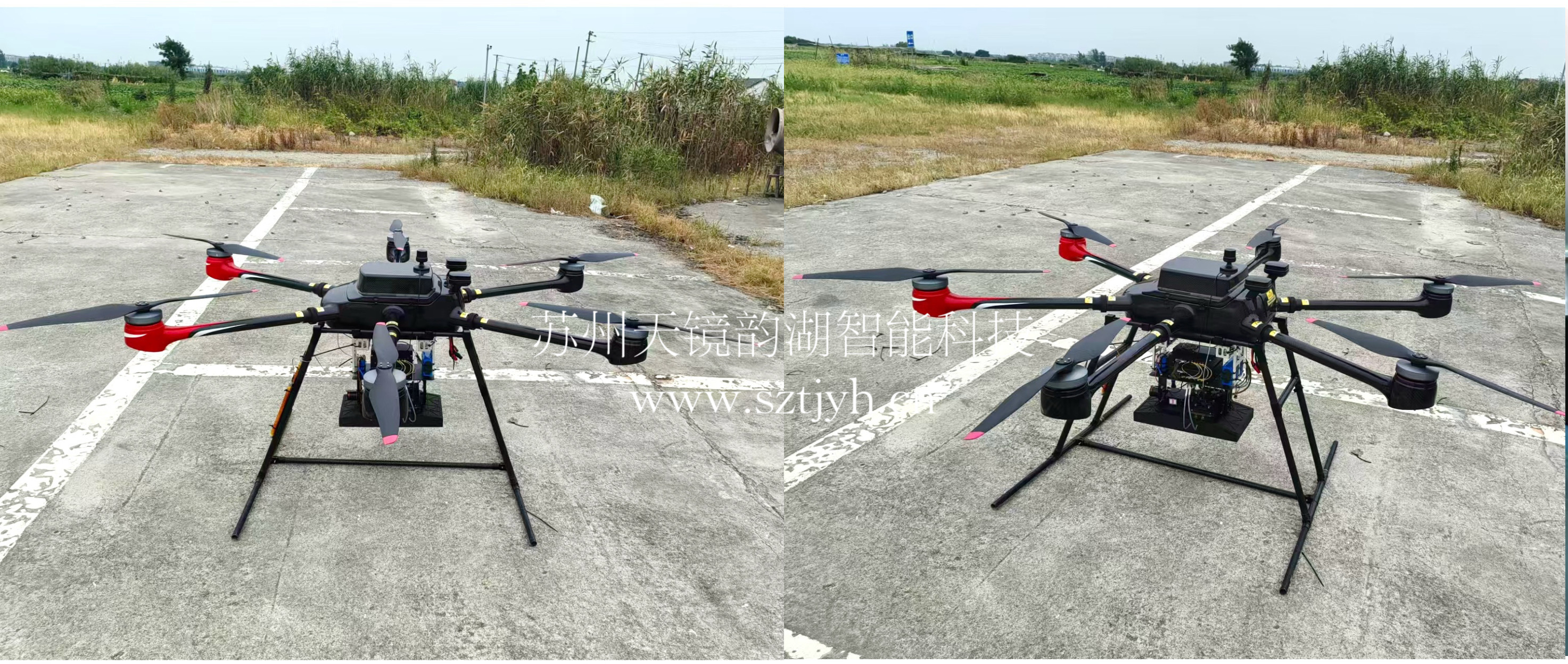

Have you ever thought that the solid earth beneath our feet is actually undergoing small and continuous "breathing" and "movement"? The city's ground is slowly sinking, the mountains are slipping quietly, and the mining areas are dented due to mining... These deformations that are difficult to detect with the naked eye may lurk huge safety risks. InSAR (synthetic aperture radar interferometry) remote sensing technology is like a pair of "clear eyes" hanging high in space. It can detect subtle changes with millimeter-level accuracy.
I. InSAR: The Technological Logic from "Dual-Image Comparison" to "Deformation Decoding"
The core principle of InSAR is that radars on various platforms emit microwaves towards the Earth's surface and receive the echoes, acquiring at least two SAR images of the same area at different times. Although the Earth's surface appears static, minute deformations cause changes in the phase of the radar echo signal.
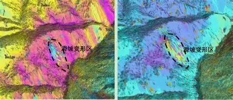
By calculating the phase difference between these two images, an "interferogram" is generated. This image is like the Earth's "fingerprint," with its interference fringes containing rich information. Through a series of complex differential processing steps, the effects of terrain undulations and flat-surface effects can be precisely eliminated, ultimately extracting the subtle deformations that occurred on the surface between the two imaging sessions. This is like having a precise "spacetime ruler," capable of measuring surface displacements completely imperceptible to the naked eye.
II. Diverse Technological Branches: The InSAR "Family" Adapted to Different Scenarios
With continuous technological development, InSAR has formed several technological branches with distinct functions, each playing an advantage in different monitoring scenarios, collectively constituting a complete InSAR monitoring technology system.
(I) D-InSAR: The "Basic Model" for Deformation Monitoring
Differential Interferometric Synthetic Aperture Radar (D-InSAR) is the core foundation of the InSAR technology system. Its key lies in removing the terrain phase from the interferogram by introducing an external DEM, thereby generating a differential map that focuses on surface deformation information. In practical applications, the interferometric phase of D-InSAR includes five components: terrain phase, flat terrain phase, deformation phase, atmospheric phase, and noise phase. Technicians remove the flat terrain effect using precise orbital data, reduce noise using filtering techniques, and then obtain integer ambiguity through unwrapping to finally obtain the surface deformation results.
However, D-InSAR technology also has significant limitations. Due to factors such as spatiotemporal incoherence and atmospheric disturbance, the monitoring accuracy of D-InSAR is easily affected by environmental interference. In rainy and foggy areas, atmospheric phase delay can significantly affect monitoring results. When the interval between two imaging operations is too long or the spatial distance is too great, changes in surface scattering characteristics may lead to signal incoherence, reducing monitoring reliability. Therefore, D-InSAR is more suitable for deformation monitoring on short timescales (several days to several years), such as coseismic deformation during earthquakes and surface displacement monitoring before and after volcanic eruptions.
(II) MT-InSAR: The "Precise Tracker" of Long-Term Deformation
To address the problems of atmospheric interference and spatiotemporal incoherence faced by D-InSAR in long-term monitoring, Temporal Interferometric Synthetic Aperture Radar (MT-InSAR) technology has emerged. It mainly includes two branches: Permanent Scatterer Interferometry (PS-InSAR) and Small Baseline Subset Interferometry (SBAS-InSAR), becoming the "main force" for long-term surface deformation monitoring.
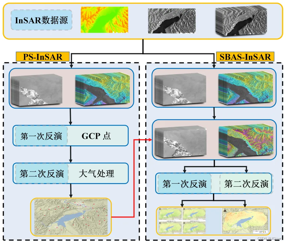
The core of A.PS-InSAR technology is to select one scene as the master image from multiple single-view complex (SLC) SAR images covering the same study area. After registering the remaining images with the master image, "permanent scatterer (PS) targets" are selected based on the stability of amplitude (intensity) and phase over time. These targets are typically man-made structures, lighthouses, exposed rocks, or artificially placed corner reflectors, whose scattering characteristics remain stable over long periods, resulting in strong echo signals. By interferometric processing and topographic removal of these PS points, differential interferometric phase based on the PS targets is obtained. Then, based on the different characteristics of the phase components, a deformation model is constructed and combined with spatiotemporal filtering to finally estimate the deformation phase and topographic phase residue.
PS-InSAR technology demonstrates outstanding performance in high-resolution urban settlement monitoring, particularly suitable for deformation monitoring of key infrastructure such as bridges, subways, and high-rise buildings. The reliability of its monitoring results has been fully verified through comparison with concurrent leveling and GPS measurement data. However, this technology also has limitations: it usually requires a large number of SAR images covering the same area (generally more than 25 images) to ensure the reliability of the model solution; and it is based on iterative regression or network review calculations of a large number of PS points, which has low computational efficiency and is not suitable for ground subsidence monitoring in large areas.
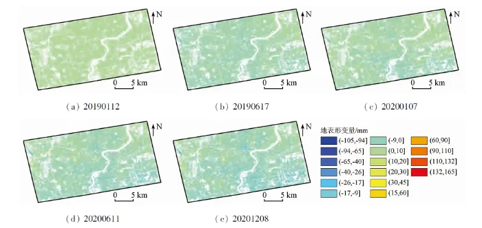
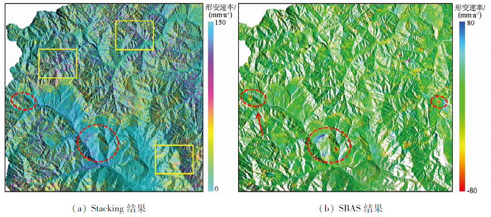
B.SBAS-InSAR technology employs a "multi-master image" approach, extracting deformation information by selecting interferometric pairs with shorter spatiotemporal baselines, effectively reducing the impact of spatial decorrelation and atmospheric delay. Its technical process consists of three steps: First, the temporal and spatial baselines are calculated for multiple SAR images of the covered area over different time periods, and suitable interferometric pairs are selected based on set thresholds; then, differential interferometry is performed on the selected interferometric pairs, and phase unwrapping is completed; finally, based on the subset of the interferograms, the deformation parameters are estimated using the least squares method or singular value decomposition (SVD). In actual processing, spatiotemporal filtering is also used to remove atmospheric delay, separating nonlinear deformation. The estimated low-frequency deformation is then superimposed with the nonlinear deformation to obtain complete deformation information for the study area.
SBAS-InSAR technology recovers deformation information by using high coherence points (selection methods include phase stability point selection method, amplitude deviation index point selection method, etc.). It can use various mathematical models such as linear model, second-order polynomial model, periodic deformation term to describe deformation law. It has significant advantages in long-term deformation monitoring over large areas. This technology is widely used in scenarios such as land subsidence surveys in the North China Plain and the Yangtze River Delta region.
(III) DS-InSAR: An Innovative Direction Breaking Through the Limitations of "Point Targets"
The emergence of Distributed Scatterer Interferometry (DS-InSAR) technology has broken the dependence of PS-InSAR on "permanent scatterer point targets." Within a radar resolution cell, if backscattering from no single scatterer dominates, such areas are called "distributed scatterers (DS)." Previously, the academic community often distinguished scatterers as "coherent targets" and "incoherent targets," weakening the physical boundary between PS and DS. DS-InSAR technology, however, is specifically designed for deformation monitoring of DS targets.
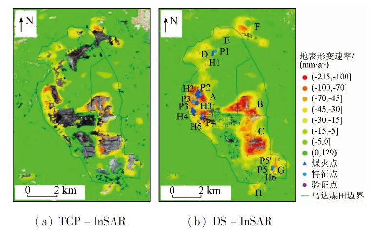
SqueeSAR (also known as "PS-InSAR V2") is a typical representative of DS-InSAR technology. Its core advantages lie in two aspects: First, through a homogeneous point selection algorithm, pixels with the same SAR statistical distribution are selected for averaging within a time-series statistical inference framework. This improves the phase signal-to-noise ratio and avoids the spatial resolution loss caused by multi-look or spatial adaptive filtering in SBAS technology, better preserving detailed information in complex scenes and reducing misclassification of deformed and non-deformed areas. Second, based on the sample covariance matrix of the complex Wishart distribution, a maximum likelihood estimation phase optimization algorithm is used to recover the phase of time-series SAR images (named "SqueezeSAR" because it requires nonlinear optimization to "squeeze" the parameters to be estimated). Furthermore, it does not rely on phase triangulation to directly solve for the time-series phase, which is fundamentally different from traditional time-series InSAR technology.
However, SqueeSAR also has limitations: the KS hypothesis test used in the homogeneous point selection algorithm has low power under small sample conditions, is prone to heterogeneous points, and has low computational efficiency; the phase optimization algorithm also faces computational efficiency issues, making it difficult to apply to large-scale, high-precision monitoring. To address this, researchers both domestically and internationally have continuously explored and improved solutions, such as employing more efficient statistical inference methods like the AD test and likelihood ratio test, utilizing singular value decomposition of the covariance matrix to improve computational speed, and introducing more robust estimators like the M estimator to ensure optimization reliability. Currently, SqueeSAR has formed the technological prototype of DS-InSAR. Broadly speaking, apart from time-series InSAR techniques based on PS point targets, most time-series methods utilize DS targets to varying degrees, providing new approaches for deformation monitoring in vegetation-covered areas, suburbs, and other regions with sparse PS points.
(IV) MAI: A Supplement to the "Three-Dimensional Perspective" of Azimuth Deformation
Traditional InSAR technology primarily acquires surface deformation information along the radar line-of-sight (LOS) direction. The introduction of Multi-Aperture InSAR (MAI) technology fills this gap in azimuth deformation monitoring. Since the azimuth and LOS directions are perpendicular, MAI technology provides a crucial supplement to D-InSAR deformation detection results, helping technicians acquire three-dimensional surface deformation information and gain a more comprehensive understanding of surface change patterns.
The principle behind MAI technology is to redetermine the zero Doppler center of SAR data using azimuth common frequency spectrum filtering, dividing a SAR image into a foreseeable and a backseeable image. These two images are then registered, processed using multi-view techniques, interferogram generated, and processed to remove flat-top effects, terrain influences, and filtering, resulting in a foreseeable and a backseeable interferogram. After differencing these two interferograms, the generated MAI interferogram contains the azimuth deformation phase information of the surface.
Compared to offset tracking methods, MAI (Magnetic Interference Imagery) offers advantages in accuracy and efficiency for azimuth deformation calculation. However, this technique also has significant drawbacks: azimuth common spectrum filtering effectively shortens the synthetic aperture time, resulting in weakened echo signals received from individual forward-looking or backward-looking images, making them susceptible to noise. Therefore, it is unsuitable for near-field coseismic deformation information extraction and rapid glacier velocity estimation. Furthermore, the vertical baseline difference between the forward-looking and backward-looking interferometric pairs leads to phase remnants caused by flatland and topographic effects in the MAI interferogram. For example, in PALSAR data, a 0.1-meter vertical baseline difference under standard swath width results in a 20° flatland phase remnant, equivalent to a 50-centimeter azimuth deformation error. In addition, the time-varying nature of ionospheric phase distribution also interferes with MAI. When the ionosphere is active, it causes azimuth shifts in the interferogram, resulting in directional "ionospheric fringes" in the azimuth deformation results acquired by MAI, a phenomenon particularly pronounced in L-band SAR data.